Failing to plan is planning to fail. Although the Aderis ClearSky PLUS™ is very simple to design for and incorporate into your project design, there are aspects of the equipment that should be considered in the initial design to avoid unnecessary costs and difficulties during construction.
The Aderis ClearSky PLUS must be installed in close proximity to the first inverter step-up transformer unit (ISU) between your Facility’s interconnection and medium voltage (MV) loop feed to support the additional secondary voltage connection the same ISU.
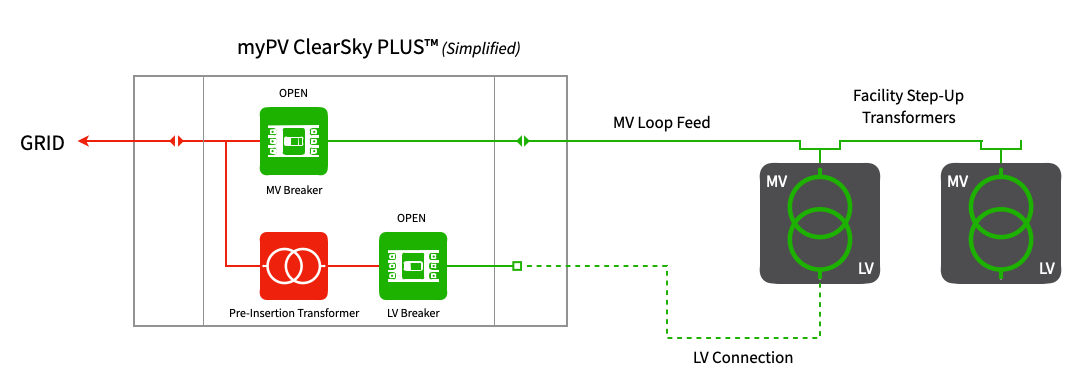
Dual, Primary and Secondary, Electrical Connections to First ISU
The Aderis ClearSky PLUS’s low profile and compact design provides Developers and Engineers and unprecedented level of flexibility regarding installation location. While many customers choose to incorporate the padmount gear into the equipment pad closest to the point of interconnection, others choose to locate the Aderis ClearSky PLUS at the Point of Interconnection (POI).
If you have concerns about the location of the Aderis ClearSky PLUS’s metering and the POI, we recommend one of the following 2 approaches:

Aderis ClearSky PLUS Located at Equipment Pad Next to First ISU
While the Aderis ClearSky PLUS is very compact, appropriate electrical, service, and door swing clearances should be considered prior to determining final pad dimensions and placement of conduits entry points.
All Aderis ClearSky PLUS Mechanical drawings provide dimensions of electrical termination cabinet conduit locations and open door swings.
Visit our Technical Documents page by registering on our Support Resources page to access the most up to date Aderis ClearSky PLUS Mechanical drawings.
